
Wind Turbine Blade Anatomy for Operators: What Actually Matters During Inspections
This article provides:
- A practical overview of wind turbine blade anatomy, materials, structural concepts & why it matters
- An explanation of the key blade zones & terminology used during inspections
- Guidance on how blade architecture influences defect interpretation and maintenance decisions
⚠️ This article complements, not replaces, OEM manuals and should always be used alongside limits, contractual requirements, and site-specific policies, providing an operator-focused framework for consistent defect interpretation and triage. It is built on SkyVisor’s experience with hundreds of thousands of defects across multiple blade models.
Blades as composites
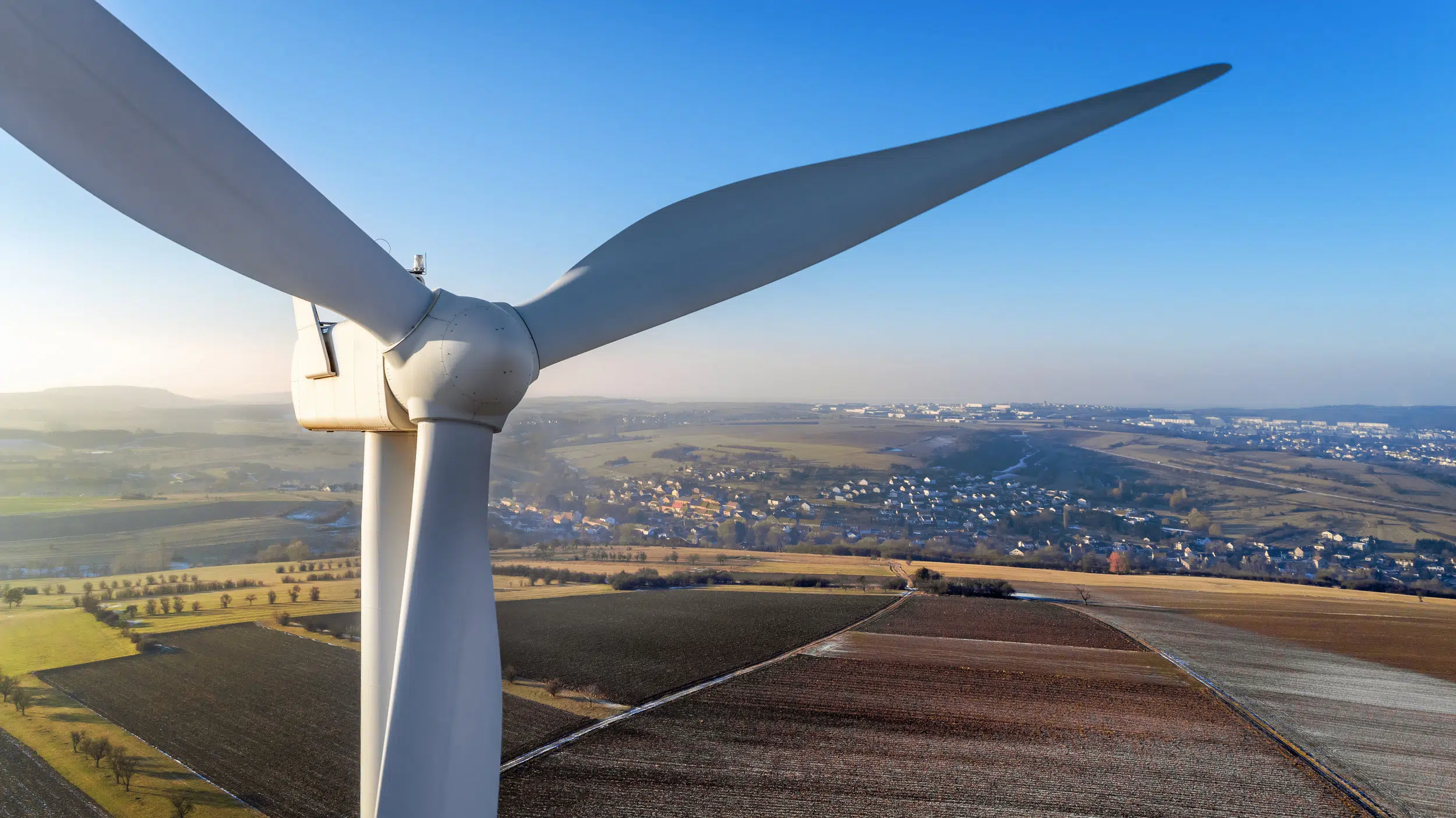
Wind turbine blade anatomy forms the foundation of every successful inspection. Understanding how a blade is constructed, where loads are carried, and how key zones are defined enables operators to locate defects accurately, assess their significance, and communicate findings consistently across teams. Without this common framework, even high-quality blade inspection data can lead to inconsistent maintenance decisions.
Blades are composite structures consisting of 85% composite material: fibres embedded in a resin matrix designed to be light, stiff, and fatigue-resistant. Defect severity is not defined by location alone. It also depends strongly on the underlying materials and protection layers at the point of damage.

© Composite materials, SkyVisor, 2026
A blade can be segmented into 4 main parts, with each part fulfilling a specific function: shell, caps, shear webs, and root.
Most blade behaviour is driven by how different layers respond to stress, fatigue, and environmental exposure. In practice, even two visually similar defects can have very different operational implications depending on which layer is affected; therefore, it is important to know what blades are made of.
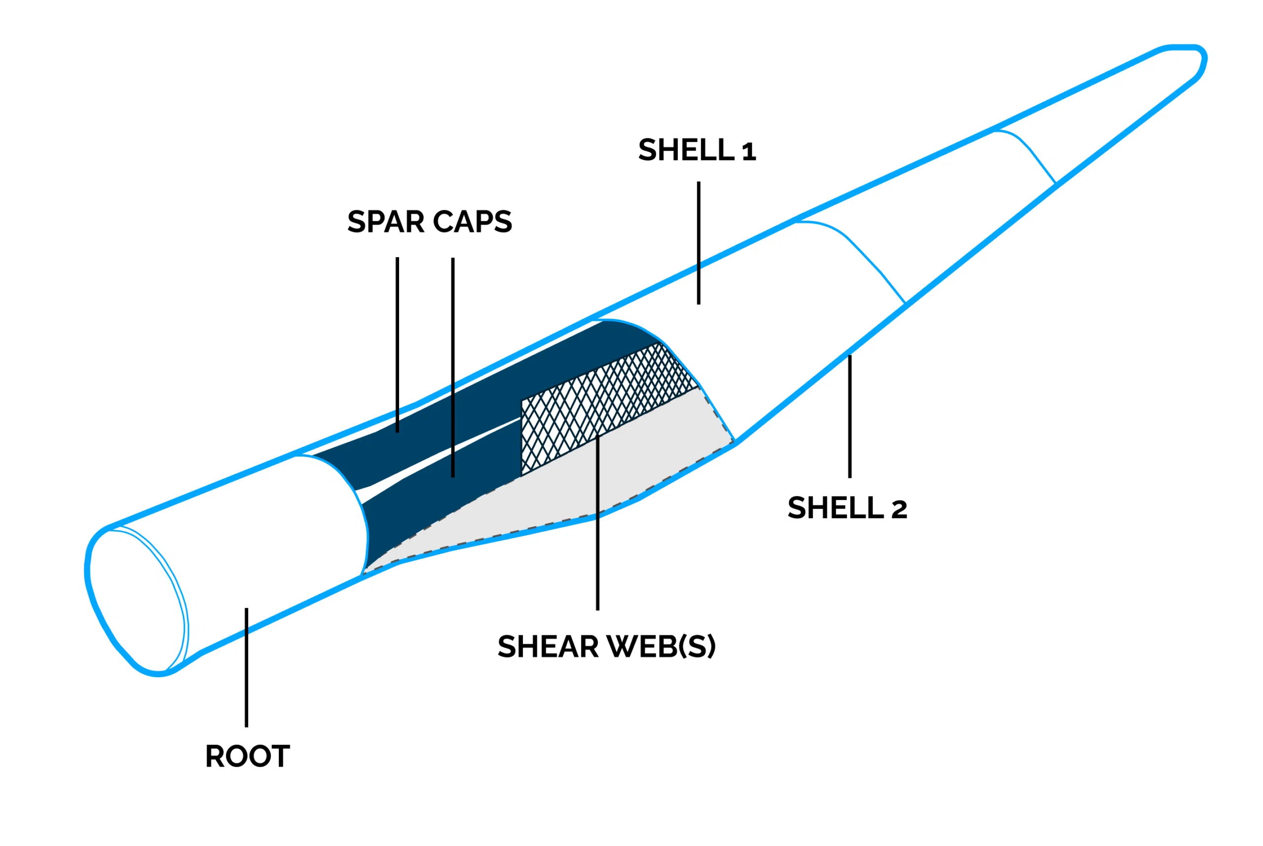
© Wind turbine blade parts, SkyVisor, 2026
Blade Materials
A wind turbine blade is not a single material, but a layered composite structure where each component has a specific role in carrying loads, protecting the surface, and resisting environmental exposure. During inspections, understanding these materials helps operators interpret what a defect may indicate and avoid treating all visible damage equally.

© Blade materials, SkyVisor, 2026
List of blade materials
Fibers
-
UD (unidirectional): continuous fibers aligned in one direction for high strength & stiffness, mainly in load-bearing areas
-
BIAX (+45°/−45°): fibers arranged diagonally to resist shear and torsional loads
-
CSM (chopped strand mat): short, randomly oriented fibers providing multi-directional reinforcement and good resin distribution

Resins
- Epoxy resin: strong and durable, excellent adhesion, high fatigue resistance
- Polyester resin: cheaper and easy to process, good mechanical properties

Core (foam/balsa)
- Balsa: wood with vertical fibre; heavier but more rigid, in contact with water, molds, used closer to the root
- PVC/PU foam: light and not water-intolerant, used on the tip

Adhesives / fillers / coating
- Epoxy adhesive: strong and durable; commonly used for bonding blade shells, shear webs, and structural repairs
- Epoxy filler: used to fill cracks, holes, dents, and surface imperfections; creates a smooth surface for finishing
- Polyurethane coating: protective outer layer; resistant to UV, moisture, weathering, and abrasion

Carbon reinforcements (when present)
- Carbon-fibre fabric: very light and stiff; used in high-load areas such as the spar caps to increase blade stiffness
- Carbon-fibre tape: unidirectional carbon fibres; provides high strength and stiffness along the main load direction
- Carbon-fibre pultrusions: pre-formed carbon-fibre profiles; used mainly in large blades to improve stiffness while keeping weight low

For example, a surface crack in a protective coating may have limited impact, while a similar-looking crack that reaches fibres, bonds, or the core structure may require a very different response. The material layer affected, combined with the defect location and progression, is what determines the potential risk.
Size: 20 x 42 cm
Drone: DJI M300 RTK
Turbine: GE 5.5 158
Size: 67 x 57 cm
Drone: DJI Matrice 4E
Turbine: Sevion MM92
Size: 18 x 42 cm
Drone: DJI M300 RTK
Turbine: Vestas V100
Size: 32 x 9 cm
Drone: DJI Matrice 4E
Turbine: Enercon E44
© Different wind turbine blade cracks, SkyVisor, 2026
Blade zones & terminology
This section defines the main blade zones used in standard inspection and operational communication. These terms are used to consistently describe locations on the blade for reporting, defect tracking, and maintenance workflows.
A clear zoning framework reduces misinterpretation, improves communication across teams and subcontractors, and supports faster, more accurate maintenance decisions.
- Blade root: The innermost section of the blade that connects to the hub using bolted joints
- Suction side (SS): low-pressure side
- Pressure side (PS): high-pressure side (NB! Vestas uses the term “windward side” to designate the pressure side)
- Leading edge (LE): wind-facing front edge
- Trailing edge (TE): rear edge
- Blade tip: The last third of the end of the blade, farthest from the hub

© Wind turbine blade parts, 2026 SkyVisor
© Blade zones, SkyVisor, 2026
Blade structural concept
Most blades consist of two shells bonded along the leading edge (LE) and trailing edge (TE). The blade is most often made from two shells made of composite (glass fibre and resin), wood, and PVC foam. The load is carried by one of two common architectures:
1️⃣ Structural spar / box spar designs
- The main load path is carried by an internal “box/tube” built from spar caps and shear webs
- This “box/tube” is made from UD fibre (often carbon)
- The shell is relatively thin, with only aerodynamic properties, and glued to it
- Impacts may crack the shell without being immediately structural.
- Internal inspections are impossible because the spar takes almost all the blade width at the root
- Most common in turbine models like: LM, Nordex, Senvion + smaller Gamesa & Vestas blades, etc.

© Box spar, SkyVisor, 2026
2️⃣ Structural shell + shear webs (spar caps)
- The shell participates more directly in load transfer.
- Certain crack shapes can be more critical.
- Can vary depending on blade design: the most common arrangement uses two shear webs of comparable height, although some blades incorporate asymmetric shear webs or a single-web architecture.
- Most common in turbine models: prefered concept for longer blades, usually used by Vestas & Gamesa, etc.

© Shear webs, SkyVisor, 2026
☝️ Why it matters: The same visible defect can imply a very different risk depending on where the primary load path runs. For example, understanding the architecture helps operators decide when a shell crack is likely cosmetic vs potentially structural, and when to escalate for internal inspection, engineering assessment, or shorter repair windows.
Conclusion
Understanding wind turbine blade anatomy is fundamental to making accurate inspection and maintenance decisions. Defects cannot be evaluated in isolation. Their significance depends on the blade zone, the underlying structural architecture, and the materials affected. Two visually similar defects may require entirely different responses depending on where they occur and how loads are transferred through the blade.
By adopting a common understanding of blade terminology, structural concepts, and inspection-critical areas, operators can improve communication across teams, standardize defect reporting, and make more consistent maintenance decisions. This shared foundation also enables more reliable defect classification, severity assessment, and repair prioritization throughout the blade’s service lifetime.
☝️ A standardized understanding of blade anatomy enables more consistent inspections and better maintenance decisions.
Useful terms
- LE: leading edge
- TE: trailing edge
- PS: pressure side
- SS: suction side
- LEP: Leading Edge Protection
- LAM: Laminates
- LPS: lightning protection system
- UD: unidirectional fiber reinforcement (fibers aligned in one direction)
- UV: ultraviolet (sunlight exposure)
- VG: vortex generator (aerodynamic add-on)
- SF: surface
- SMT: Solit Metal Tip
- BDL: Bonding lines
- LGH: Lightning
- FTS: Add-ons
Want to download the full list of useful abbrevations?
About the SkyVisor Wind Suite
SkyVisor Wind is a comprehensive wind asset management and blade inspection platform that empowers asset owners and operators to bring inspections in-house and take full control of their blade maintenance program.
By combining automated drone inspections, AI-powered defect detection, advanced blade analytics, and streamlined reporting, SkyVisor enables teams to inspect turbines faster, reduce reliance on third-party service providers, and make confident, data-driven maintenance decisions.

Get in touch to discover how easy it is to perform professional wind turbine blade inspections with your own team.
Wind | Blades
Reduce downtime and increase your blade awareness
Solar | Thermography
Maximize the performance of your solar park
Solar | Construction
Monitor the construction process of your PV plant